
Hydraulic Systems in Heavy Machinery: Troubleshooting Common Issues
Modern heavy machines depend extensively on powerful hydraulic systems for their performance, reliability, and power output. These heavy-duty machines like crawler excavators, mining hauling trucks, and industrial loaders are entirely dependent on complex hydraulics to operate high-tonnage loads with great precision. User manuals on Hydraulic Systems in Heavy Machinery: Troubleshooting Common Issues are significantly helpful in increasing the production efficiency of such work machines by preventing costly operational outages and unplanned breakdowns.
Importance of Hydraulic Systems in Heavy Machinery
Resolving fluid power problems is part of a comprehensive skill set that can benefit not only field mechanics but also workshop managers and industrial operators. Creating well-structured methods through which hidden defects can be identified, component wear can be measured, and heavy equipment serviced will help earthmoving machines to function optimally even in the most extreme external conditions.
Hydraulic circuitry comprises of intricate, high-pressure fluid systems. Hence, a mere external inspection is not enough to understand the fluid circuit completely. A well-organized, systematic process that efficiently correlates the symptoms of a machine unpleasantly responding such as rapid loss of pressure, temperature increase, and vibration with the actual physical problem should be illustrated.
Referring to Hydraulic Systems in Heavy Machinery: Troubleshooting Common Issues as simplified and well-structured reference manuals can substantially accelerate the diagnostic phases, help pinpoint malfunctioning valves or deteriorated pumps effectively, and assist heavy machinery hydraulics safely achieve their performance level once again.
Understanding the Architecture of Heavy Equipment Hydraulics
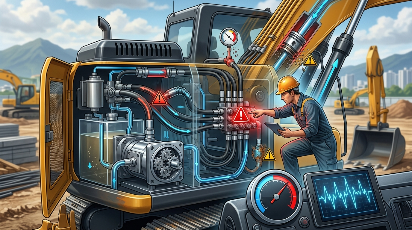
The basic mechanical concept that makes a hydraulic system work is converting a low mechanical force input into a very high mechanical force output through the use of a special liquid working under pressure. The major circuit operations depend on a closed loop that starts with the main fluid reservoir which stores, cools, and cleans the fluid.
Then a pump driven by the engine pumps the fluid into the main high-pressure lines. These lines feed the fluid directly to multi-spool directional control valves which regulate fluid direction, pressure limiting valves, and flow balancing controls before reaching the heavy cylinders or rotary drive motors to carry out the mechanical work.
Fluid cleanliness and quality must be maintained throughout this enclosed hydraulic circuit since any slight change in flow can result in significant reduction of system efficiency together with sudden performance decline in the whole machine fleet. When the steps involved in making a guide to Hydraulic Systems in Heavy Machinery: Troubleshooting Common Issues
are considered, one of the most helpful things is the mapping of the exact flow path so that the technicians may as well identify the points of system faults without any hesitation.
- Fluid Reservoirs: Not only do they store fluid capacity but also the tanks are designed to support air elimination, allow fine solid particles to settle, and to get rid of thermal energy radiation through extended wall surfaces.
- Engine-driven Pumps: The engine pump is the main mechanical source of power which converts the rotational torque supplied by the diesel engine into the hydraulic working fluid flow and pressure.
- Control Valves: Heavy machinery hydraulic control valve grids highly complicated and require correct spool positioning to accurately regulate, proportion, and redirect high volume flows of pressurized fluid to different machine members.
Identifying and Resolving System Overheating
Extended operating time under heavy loads often results in hydraulic system overheating which adversely affects fluid power components. Thermal load exceeding the design capability of fluid media causes significant viscosity degradation leading to lubricating film thinning on the surfaces of the fluid system components and thus the accelerated wear of sealing materials, valve spools, and gears in pumps takes place.
The excessive heating of fluid is followed by increased internal oil bypass in pump slits, hotspot generation, and irreparable damage of expensive parts. Monitoring operating temperature is one of the most effective ways of controlling the fluid power system, not to mention, it touches on what’s considered to be the staple gear when delving into Hydraulic Systems in Heavy Machinery: Troubleshooting Common Issues.
Table: Hydraulic Systems in Heavy Machinery
| Symptom / Indicator | Potential Thermal Root Cause | Immediate Remedial Action |
| Drastic Fluid Viscosity Loss | Heat exchanger cooling fins blocked by mud, dirt, or heavy operational debris. | Power-wash external radiator cores and clear air blockages. |
| Accelerated Cylinder Seal Failure | Internal relief valve pressure limits set too low, causing continuous fluid bypass. | Recalibrate system relief valve cracking pressures back to factory standards. |
| Slowing Moving Component Speed | Worn internal pump rotating groups generating high friction and oil bypass. | Conduct a full pump case-flow test to evaluate component wear. |
- Clean External Cooling Elements: Include in your daily maintenance routine the task of removing all accumulated mud and other debris from the cooling fans and radiator fins to maximize the air flow.
- Inspect Internal Relief Valve Configurations: Double-check system relief pressure values to ensure they do not exceed or fall below the intended factory levels and that the motors do not vent constantly which can create high frictional heat.
- Evaluate Return Line Restriction Levels: It is important to check the return lines to ensure the flow is not restricted at any point along the line which would cause backpressure and therefore higher oil temperatures.
Diagnosing Unusual System Noises and Pump Cavitation
Heavy equipment pumps producing unusual sounds like popping, banging, or metallic whining are usually an indication of a severe problem that needs urgent fixing. Such distinct and disruptive noises are mostly caused by two closely related factors: aeration (the fluid contains trapped air) or cavitation (vapor bubbles are created and violently collapse in high-pressure chambers).
When that deteriorating mechanism goes unnoticed, it is observed through pump cavitation diagnosis procedures that the operation of a microscopic hammer is the result of the phenomenon, the matrices of which are the continuous metal exposure on pump impellers, cylinder walls with the feature of pitting, and the distribution of the smallest metallic particles throughout the entire system.
That is why early intervention is very important so that air leaks and pressure drops don’t turn into very severe damages to the main pump components. Noise anomalies, in particular, are part of the Hydraulic Systems in Heavy Machinery: Troubleshooting Common Issues documentation, which also states that they should absolutely be taken seriously.
- Verify Fluid Intake Connection Tightness: Check thoroughly to be sure that there are no suction-line air leaks by ensuring that the fluid reservoir to pump inlet line’s suction line clamps, flange bolts, and fittings are all tightly sealed.
- Inspect Suction Strainer Blockages: Avoid issues with restricted intake flow and vacuum-induced fluid vaporization by cleaning the internal reservoir suction strainers regularly.
- Examine Reservoir Fluid Levels: Proper heavy machinery operation at a steep angle can be ensured by keeping the intake pipe submerged deeply through maintaining correct fluid volume levels inside the main sight glass.
Mitigating Fluid Contamination and Internal Component Wear
Continued particulate and moisture contamination among other issues are very significant contributors to the premature failure of heavy-duty fluid systems all over the world. Microscopic-sized particles such as sand grains, metal shavings, and fine dust are used as abrasives and thus they scratch polished valve spools, score cylinder rods, such that the internal tolerances are widened until that time when the components are unable to hold pressure.
On the other hand, water getting inside whether open to a humid environment or being washed down directly results in fluid chemistry degradation, corrosion, and a milky emulsion that leads to lubrication property loss.
In other words, the fluid contamination control should be the main focus of a stringent program aimed at extending the operating life of high-pressure machinery components. The step of fluid contamination control is what remains essential to a reliable hydraulic troubleshooting guide.
Contamination Sources:
- Built-in (Welding slag, assembly dirt)
- Ingressed (Damaged breather caps, worn wiper seals)
- Internally Generated (Metallic wear particles from friction)
Upgrade System Breather Caps: Replace standard reservoir caps with high-efficiency desiccant breathers to capture both fine airborne dust particles and incoming environmental moisture.
Stick to Differential Filter Testing Schedules: Use differential pressure gauges to check the filter condition and change the filter elements based on the actual level of restriction rather than relying on simple hour-count intervals.
Enforce Strict Fluid Handling Cleanliness: Make use of dedicated filter carts and cleaned transfer tools when refilling systems to avoid contamination from new oil drums.
Troubleshooting Erratic Actuator Movement and Pressure Drops
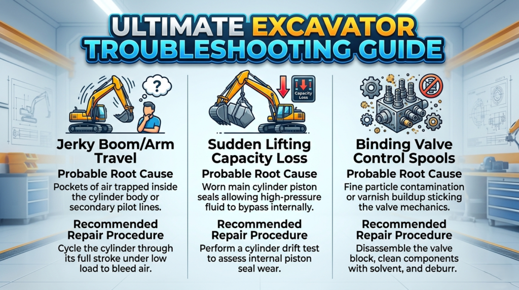
Heavy excavators, loaders, or drilling rigs may sometimes have a problem with their jerk movements of boom or sudden loss of lifting capacity. Most of the time, deep pressure drops or sticking valve mechanisms are the causes of such issues.
The main reason for a confused actuator may be the presence of air trapped inside the cylinder barrels or the internal directional spools may be so binding due to slight physical distortions or buildup of varnish. A step-by-step hydraulic pressure drop test at control blocks by mechanic can help identify the exact restricted location.
This separate the one-off industrial valve repair situations from a widespread pump performance failure.
This structural isolation is fundamental to mastering Hydraulic Systems in Heavy Machinery:
| Diagnostic Area | Probable Root Cause | Recommended Repair Procedure |
| Jerky Boom/Arm Travel | Pockets of air trapped inside the cylinder body or secondary pilot lines. | Cycle the cylinder through its full stroke under low load to bleed air. |
| Sudden Lifting Capacity Loss | Worn main cylinder piston seals allowing high-pressure fluid to bypass internally. | Perform a cylinder drift test to assess internal piston seal wear. |
| Binding Valve Control Spools | Fine particle contamination or varnish buildup sticking the valve mechanics. | Disassemble the valve block, clean components with solvent, and deburr. |
- Execute System Air Purge Cycles: Bleed trapped air from the network by cycling all cylinders through their full range of movement several times under light operational loads.
- Conduct Periodic Cylinder Drift Evaluations: Isolate individual cylinders under full rated loads to measure rod movement via a cylinder drift test, helping identify internal piston seal bypass.
- Check Pilot Control Pressure Stabilities: Measure pressure outputs from the primary pilot pump to ensure your joysticks are sending strong, steady signals to the main valve spools.
Advanced Online Machinery Preventive Maintenance Systems
Basic reactive maintenance may cause busy businesses to incur significant operating expenses and protracted field downtime. Maintenance staff may use digital sensors and automated data tools to monitor the system health in real time, moving towards a proactive approach based on equipment online monitoring.
Fleet managers may continually check fluid temperatures, pressure levels and particle counts to discover early indications of component wear, plan maintenance before failure occurs, and extend the lifespan of their fluid power maintenance programs. By implementing these sophisticated preventive maintenance techniques, the knowledge gained from the study of Hydraulic techniques in Heavy Machinery: Troubleshooting Common Issues is performed before to catastrophic failures.
- Install Continuous Pressure Transducers: Put digital pressure sensors in strategic locations along high-pressure lines to spot rapid increases or decreases that lead to problems with valves or pumps.
- Install Real-Time Oil Quality Monitors: Use inline fluid sensors to monitor changes in fluid clarity, moisture and temperature while in operation.
- Integrate Heavy Equipment to a Centralized Telematics: Use cloud-based diagnostic platforms from machinery online networks to analyze operational data remotely, allowing early troubleshooting from a central workshop.
FAQs – Hydraulic Systems in Heavy Machinery Troubleshooting Issues
How can I tell if my heavy equipment hydraulic pump is failing?
The hydraulic pump will run into progressive failure issues if its symptoms are ignored. One of the earliest behavioral changes following the loss of component integrity is a metallic, high-pitched continuous or intermittent noise such as cavitation induced buzzing, flowing through different pipe tracks. Other operating changes leading to a malfunction would be lower or slower running speed, unresponsive joystick controls, and rise in temperature levels due to heavy internal oil bypass within the pump housing.
What causes a hydraulic system to overheat, and how do I fix it?
The heating problem in the system arises due to the overall incapacity of heat dissipation by cooling components of the system because the system keeps on generating heat. The usual causes for the same are the blockage or contamination of the heat exchanger fins, relief valve pressure limits inaccurately set causing the continuous fluid bypass or wrong viscosity oil for your operating environment usage. So, cleaning radiator fins, adjusting relief valves at factory standards, and matching your fluid to climate are the ways to deal with it in your heavy equipment maintenance program.
Why are the hydraulic cylinders on my machinery moving erratically or shaking?
Usually jerky or unstable cylinder motion is due to the presence of air bubbles suspended within the hydraulic fluid and/or cylinders. Because of the compression qualities of air, this leads to sudden jerks and dips in motion under varying load levels. Other causes could be valves sticking with discarded directions or the occasional wear and tear of the guide bands inside the cylinder along with the effect of friction too on the joints preventing free movement when not adequately lubricated.
How often should hydraulic fluid and filters be changed on heavy machinery?
Inevitably, the most common approach to maintain hydraulics in heavy machinery aims at changing components based on time, i.e., by the hour count only. However, the industry standard today has shifted to making changes based on fluid analysis and differential pressure readings. Typically, pilot and return line filters are changed roughly between 250 to 500 operating hours, while main hydraulic fluid changes occur approximately every 1500 to 2000 hours depending on operating environment severity and fluid testing results.
What is the difference between hydraulic aeration and cavitation?
Both aeration and cavitation problems involve air and fault the system performance but originate from very different causes. Aeration refers to the mixing of airline oil due to the presence of loose suction fittings, grounding of seals in the shaft, low reservoir levels, etc. A good pump cavitation diagnosis will be able to tell you that cavitation is caused when pump intake restrictions or high vacuum levels result in the fluid vaporizing, thus bubbles being formed which then condensate with enormous force when entering high-pressure zones.

